




Paul Glorieux

Aero-Hydrodynamics Engineer

3D Models

CFD Projects

Drag to rotate · Scroll to zoom

2026

Aerofoil and 3D wing shape optimisation

Optimisation algorithm based on low-fidelity flow solvers ESDU VGK (2D) and ESDU VFP (3D), developed in Python during my Master Thesis at Cranfield University. Included the development of a Graphical User Interface (GUI).

Industrial partners
AIRBUSAIRBUS

The objective of this project was to develop a computationally efficient aerofoil optimisation framework for the preliminary design of transonic wings. The algorithm was developed with Python and connected to the ESDU VGK and VFP low-fidelity aerodynamic solvers, allowing a large number of candidate geometries to be evaluated without the computational expense associated with RANS simulations.

Each aerofoil is described using a reduced set of design variables that control the upper and lower surface geometry. This provides enough freedom to modify the pressure distribution and aerodynamic behaviour while maintaining smooth and physically realistic shapes throughout the optimisation process. The aerodynamic performance of each candidate aerofoil is evaluated using the ESDU Viscous Garabedian–Korn solver. VGK combines a transonic full-potential flow solution with an integral boundary-layer model, enabling it to predict viscous drag, shock-wave behaviour and the onset of transonic drag rise at a very low computational cost.

A genetic algorithm is used to explore the design space and identify improved aerofoil geometries. At each generation, a population of candidate designs is created, evaluated and ranked according to the selected aerodynamic objective. The best-performing solutions are retained and used to generate new candidates until the convergence criteria are reached. The framework can optimise the aerofoil by increasing lift and/or reducing drag while imposing fixed or variable thickness and minimum leading edge radius value, or maximising the Korn factor.

For a three-dimensional wing, the selected spanwise aerofoil sections are extracted and converted into equivalent two-dimensional design conditions. Local sweep and flow effects are taken into account before each section is optimised. The modified aerofoils are then reintroduced into the wing geometry for analysis with ESDU VFP. The complete workflow was integrated into a graphical user interface, allowing the user to import an aerofoil or wing, define the flow conditions, select the objective and geometric constraints, and control the optimisation settings. The interface also provides direct comparisons between the original and optimised geometries and their aerodynamic performance.
Drag to rotate · Scroll to zoom

2024

Virtual Towing Tank CFD - SYSSER Hull

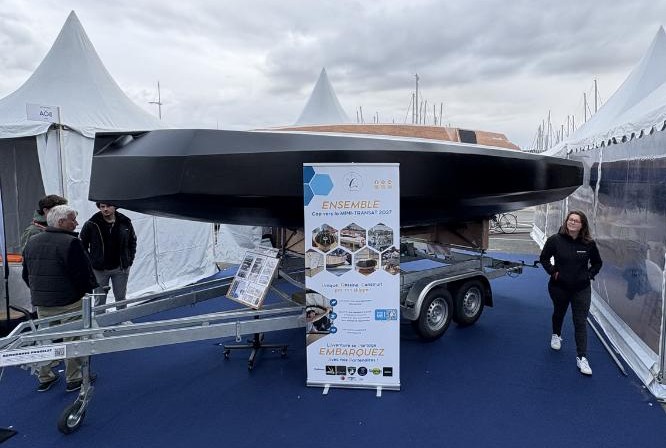
Developed in STAR-CCM+ during my internship at Gildas Plessis Yacht Design to validate predictions against towing-tank data and assess the performance of the Greenscow 650, an innovative wooden Mini-class offshore racing yacht.

Industrial partners

Gildas Plessis Yacht Design & Associés
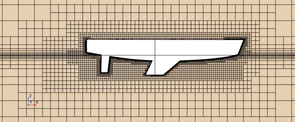
Side view of the SYSSER hull computational mesh
Greescow 650 at Grand Pavois 2025. Source: Yannick Eudeline

The objective of this project was to develop a Virtual Towing Tank simulation in STAR-CCM+ capable of predicting the hydrodynamic resistance and free-surface behaviour of sailing-yacht hulls. The methodology was first established using the KCS reference hull, for which experimental towing-tank data were available.

The simulation used an unsteady, multiphase Volume of Fluid approach to model the interaction between water and air. Turbulence was represented using the k-epsilon model, while gravity, wave generation and wave absorption were included to reproduce the free surface and the resulting wave system. A trimmed-cell mesh was refined around the hull, the water surface and the wake, with progressive transitions between refinement regions to maintain numerical stability and control computational cost.

The validated methodology was then adapted to the SYSSER 60 sailing-yacht hull using experimental data published by Delft University of Technology. Unlike the initial symmetric KCS case, the complete domain was modelled so that upright and heeled configurations could be analysed. The Dynamic Fluid–Body Interaction option was removed to reduce computational cost, meaning that the hull remained fixed at its prescribed attitude throughout each simulation.

A total of 18 mesh-control regions were created and positioned relative to the hull so that the refinement strategy automatically followed changes in heel angle. These regions concentrated cells around the hull, the air–water interface and the wake, while also ensuring gradual transitions towards the coarser outer domain. Separate meshes were generated for the upright configuration and for the hull at 10 degrees of heel.

Side view of the SYSSER hull computational mesh
Side view of the mesh-refinement regions around the SYSSER hull and free surface.

Mesh-independence studies were carried out for both configurations using total resistance as the convergence criterion. The final simulations differed from the experimental towing-tank measurements by only 0.3% for the upright hull and 0.4% at 10 degrees of heel. These results provided strong validation of the selected physical models, domain dimensions and mesh-refinement strategy before applying the methodology to the Greenscow 650.

Drag to rotate · Scroll to zoom

2026

3D Viscous Panel Method for Yacht Appendages

Developed in Python, this 3D viscous panel method provides rapid hydrodynamic predictions for yacht appendages, with automatic geometry generation and adaptive meshing.

The objective of this project was to develop a fast three-dimensional method for predicting the hydrodynamic performance of sailing-yacht appendages such as rudders, keels and hydrofoils. The geometry is generated parametrically from airfoil sections and three-dimensional leading- and trailing-edge curves, allowing a wide range of shapes to be created and analysed.

The appendage surface is discretised automatically using a structured panel mesh. The spanwise distribution is adapted to the local curvature of the geometry, with additional refinement near the root and tip, where pressure gradients and three-dimensional flow effects are more sensitive. A wake is then generated downstream from the trailing edge to apply the Kutta condition.

The flow solver combines a source-and-doublet panel method with a strip-wise integral boundary-layer model. The inviscid solution provides the surface velocity and pressure distribution, while the boundary-layer calculation estimates transition, separation, displacement thickness, skin friction and viscous drag. Both solutions are coupled iteratively to account for the influence of the boundary layer on the external flow while maintaining a very low computational cost.

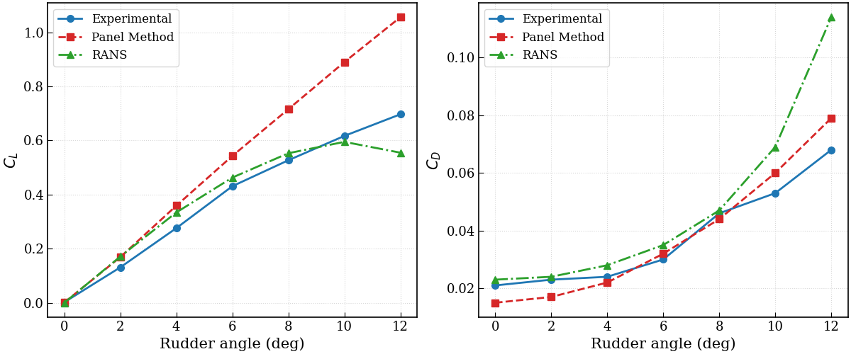
Validation of the viscous panel method using a TP52 rudder
Comparison of experimental, viscous panel-method and RANS results for a TP52 rudder.

The methodology was validated using experimental and RANS data from a TP52 rudder study performed by Jorge Izquierdo Yerón. Simulations were performed over rudder angles ranging from 0° to 12°. The predicted lift coefficient follows the experimental trend closely at low and moderate angles, while the drag evolution is also reproduced consistently across most of the tested range.

At the highest rudder angles, the panel method increasingly overpredicts lift because strong separation and stall cannot be fully represented by the potential-flow formulation and direct boundary-layer coupling. The results nevertheless confirm that the method is suitable for rapid preliminary design and performance comparisons within attached and mildly separated flow conditions.

Drag to rotate · Scroll to zoom

2026

NASA CRM in Transonic conditions

RANS simulations of the NASA Common Research Model in transonic conditions, performed in ANSYS Fluent using a Pointwise mesh to assess lift, drag and shock-wave behaviour against wind-tunnel data.

The objective of this project was to assess the ability of Reynolds-Averaged Navier–Stokes simulations to reproduce the aerodynamic behaviour of the NASA Common Research Model under transonic conditions. This wing-body configuration is widely used by the AIAA Drag Prediction Workshops as a reference case for evaluating CFD methods on modern transport-aircraft geometries.

The mesh was built using Pointwise and the simulations were carried out in ANSYS Fluent at a freestream Mach number of 0.85 and a Reynolds number of 5 million. A density-based solver was selected to capture compressibility effects, local supersonic regions and shock waves. The solution procedure was progressively advanced from first-order explicit settings to a second-order implicit formulation using the Roe flux-difference splitting scheme.

Particular attention was given to the k–ω SST turbulence model, which combines the near-wall behaviour of the k–ω formulation with the improved freestream robustness of the k–ε model. This makes it suitable for transonic flows involving adverse pressure gradients, shock–boundary-layer interaction and possible shock-induced separation.

The computational mesh was refined around the wing leading and trailing edges, the wing–fuselage junction, the tip, the expected shock location and the downstream wake. The first-cell height was selected to maintain y+ below one, allowing the boundary layer to be resolved directly. A grid-convergence study confirmed that the aerodynamic coefficients were effectively independent of further mesh refinement.

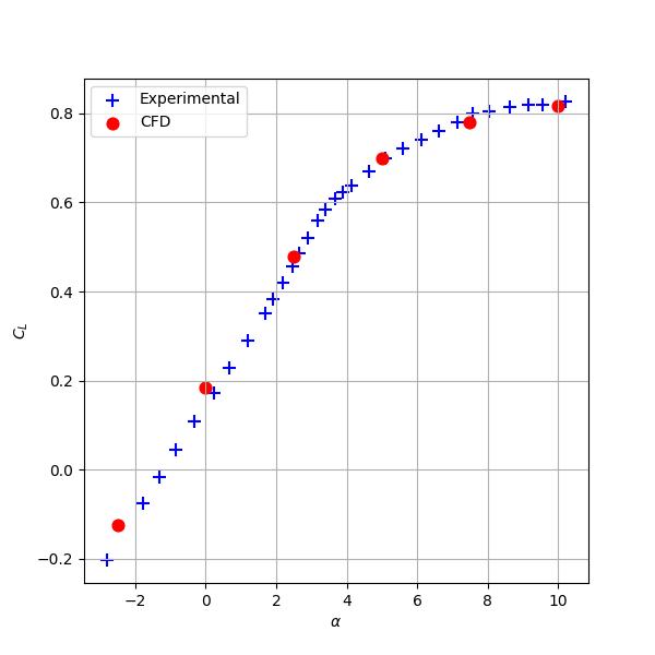
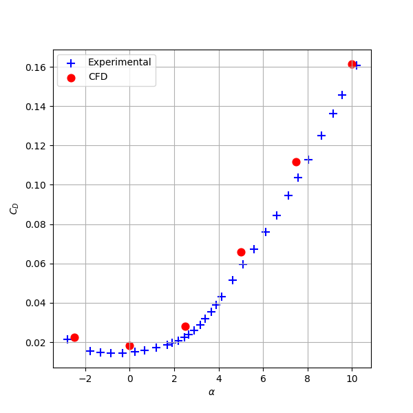
Comparison of experimental and CFD lift coefficient for the NASA CRMComparison of experimental and CFD drag coefficient for the NASA CRM
Comparison of experimental and k–ω SST CFD lift and drag coefficients across the investigated angle-of-attack range.

The CFD predictions were compared with wind-tunnel measurements over a range of angles of attack. Lift was slightly overpredicted at low incidence and underpredicted above approximately 5°, while drag remained moderately overpredicted throughout the analysed range. Overall, the study demonstrated that the k–ω SST model can provide useful predictions of lift, drag and shock behaviour for the NASA CRM at transonic conditions.

Experimental Studies

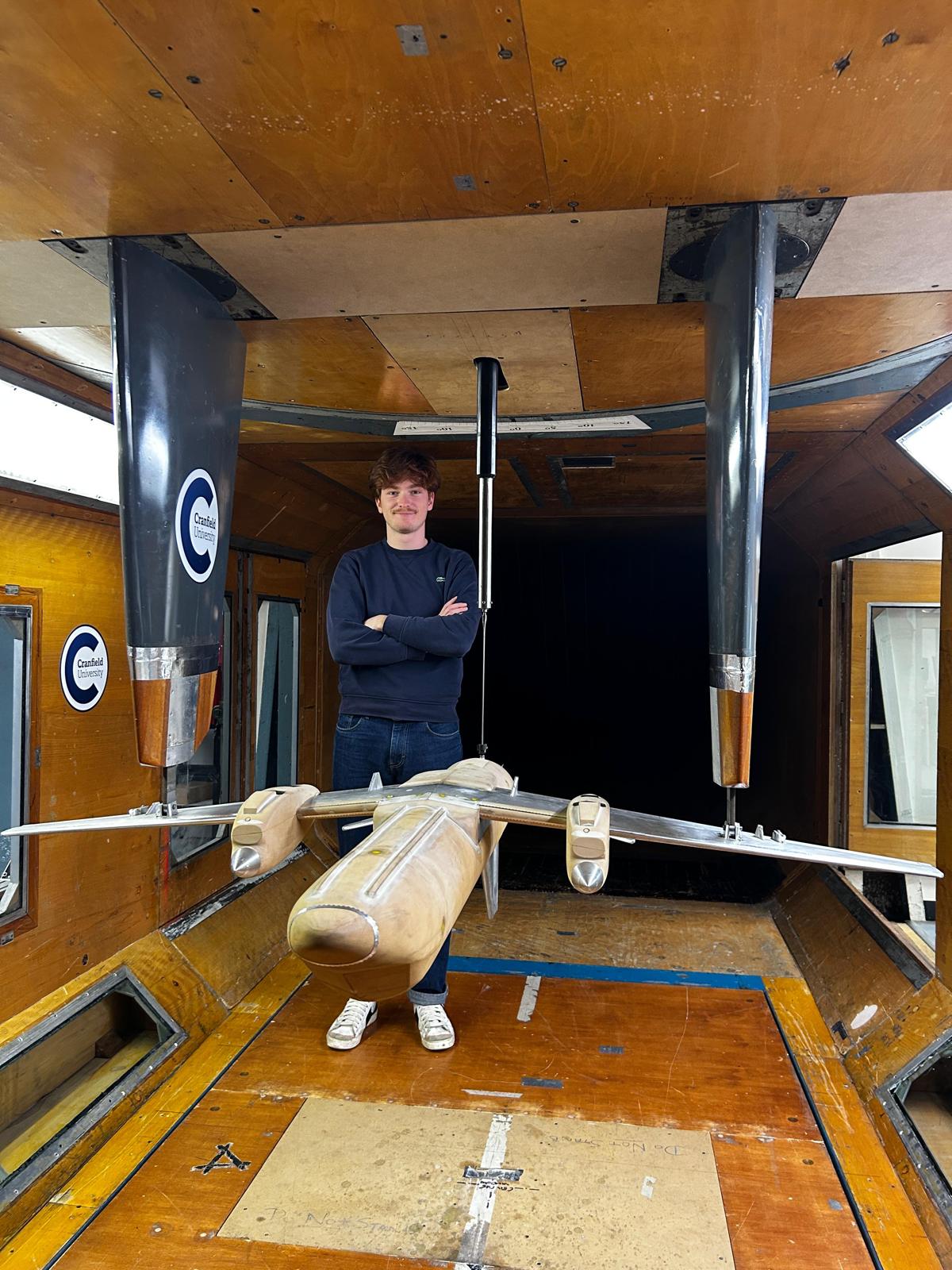
SAAB 340B model installed in the wind tunnel

2026

SAAB 340B Wind Tunnel Testing

A 1:14-scale SAAB 340B model was tested in the Cranfield 8 × 6 wind tunnel to investigate its aerodynamic behaviour with a 10° rudder deflection. The model was mounted on an external aerodynamic balance, allowing lift, drag and pitching moment to be measured over a range of angles of attack. Wind-off and tare measurements were used to correct the recorded forces and remove the influence of the model support and experimental installation.

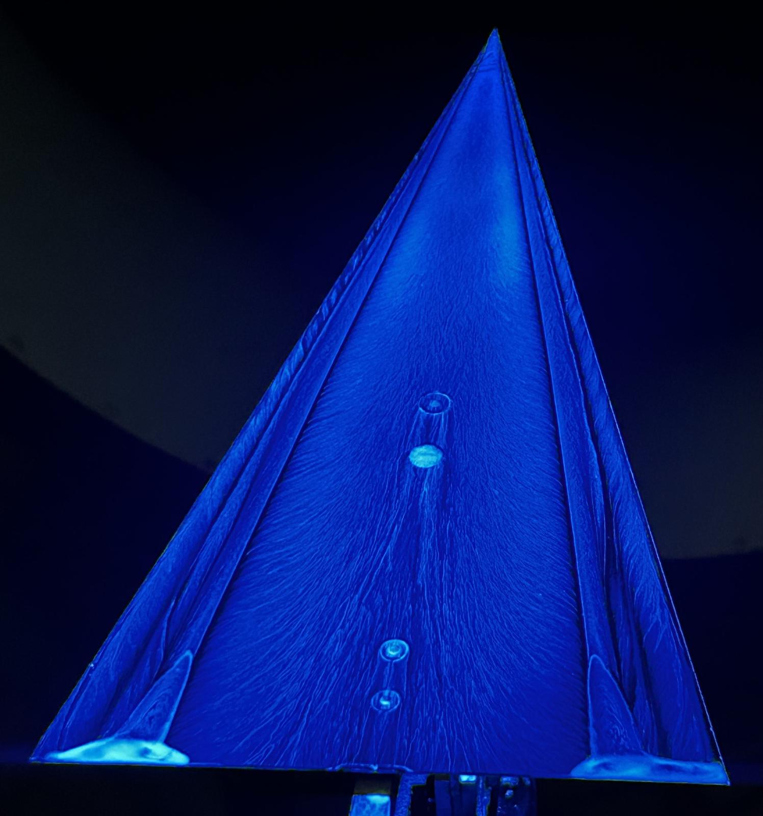
Surface-flow visualisation over a delta wing

2026

Delta Wing Flow Visualisation

A slender delta wing was tested in the Weybridge open-section wind tunnel to study its aerodynamic performance and the vortex-dominated flow developing above its upper surface. Lift, drag and pitching moment were measured with a six-component strain-gauge balance over angles of attack ranging from 0° to 38°. Wind-off tare measurements were applied to correct the recorded forces for the influence of the model support.

Surface-flow visualisation was used to observe the separated shear layers generated at the sharp leading edges. These shear layers rolled up into a pair of concentrated vortices above the wing, creating a strong suction region and producing additional vortex lift as the angle of attack increased. This mechanism allowed the delta wing to maintain significant lift at angles well beyond the conventional stall range of a straight wing.

Other Projects

2026

HullCAD — Yacht Design Software

Development of an interactive yacht-design application combining parametric hull modelling, hydrostatic analysis and three-dimensional visualisation within a single interface.

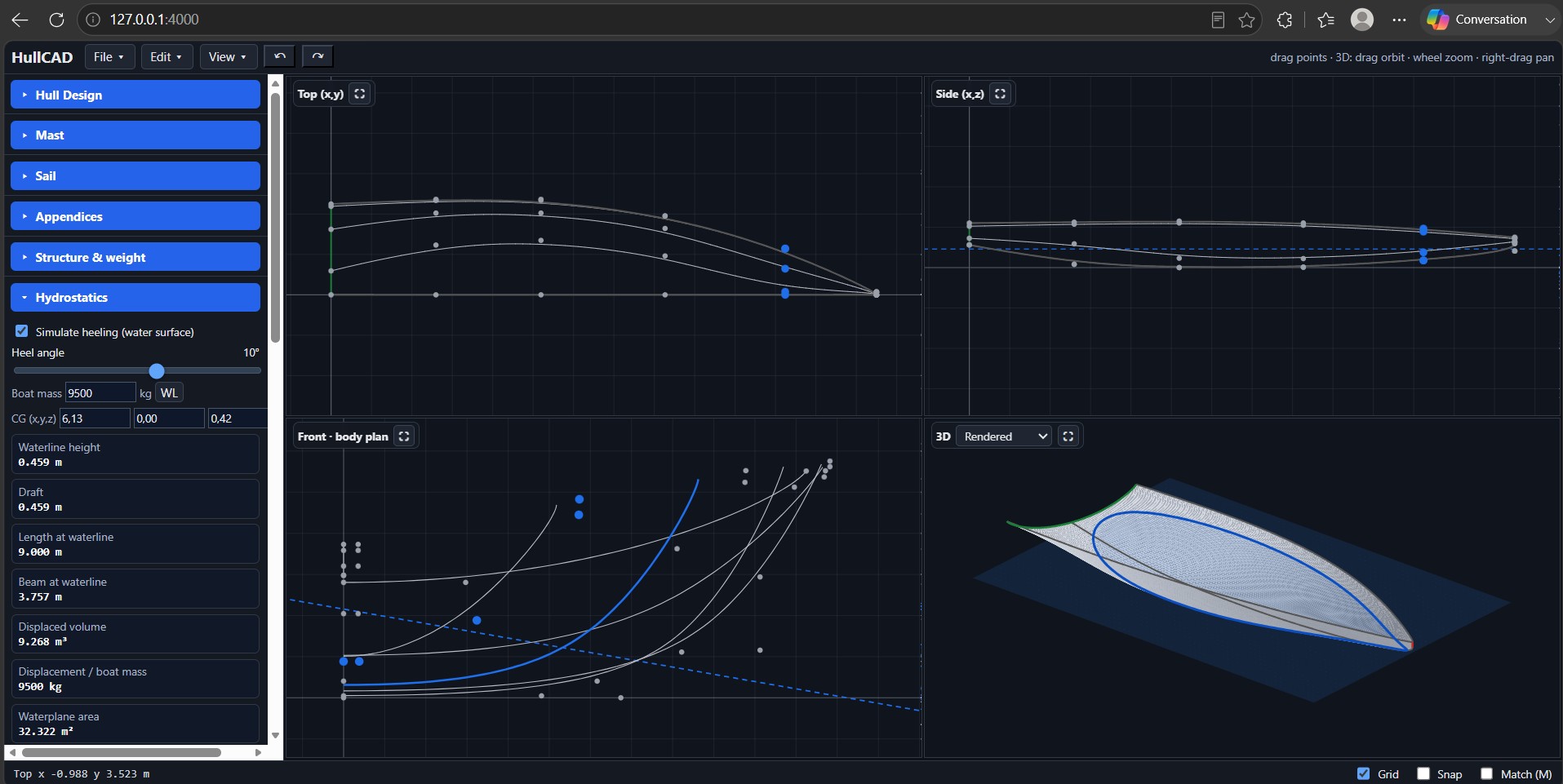
HullCAD yacht design software interface

HullCAD is an interactive yacht-design application developed to bring the principal stages of preliminary hull design into a single interface. The hull is represented using smooth B-spline and NURBS geometry, allowing its main dimensions and local shape to be modified directly through editable control points.

The application automatically calculates the principal hydrostatic characteristics of the current design, including draft, waterline length, waterline beam, immersed volume, displacement and waterplane area. These calculations can also be performed for different heel angles and water-surface positions, allowing the evolution of the immersed geometry and hydrostatic behaviour to be assessed directly during the design process.

Additional modules support the preliminary definition of the mast, sails, appendages, internal structure and weight distribution. The software can also generate a traditional lines plan and export the resulting geometry as OBJ, IGES or STEP files. In particular, the IGES and STEP exporters generate NURBS surfaces that can be imported into external CAD software such as CATIA or Rhinoceros for further modelling, structural development, rendering or numerical analysis.